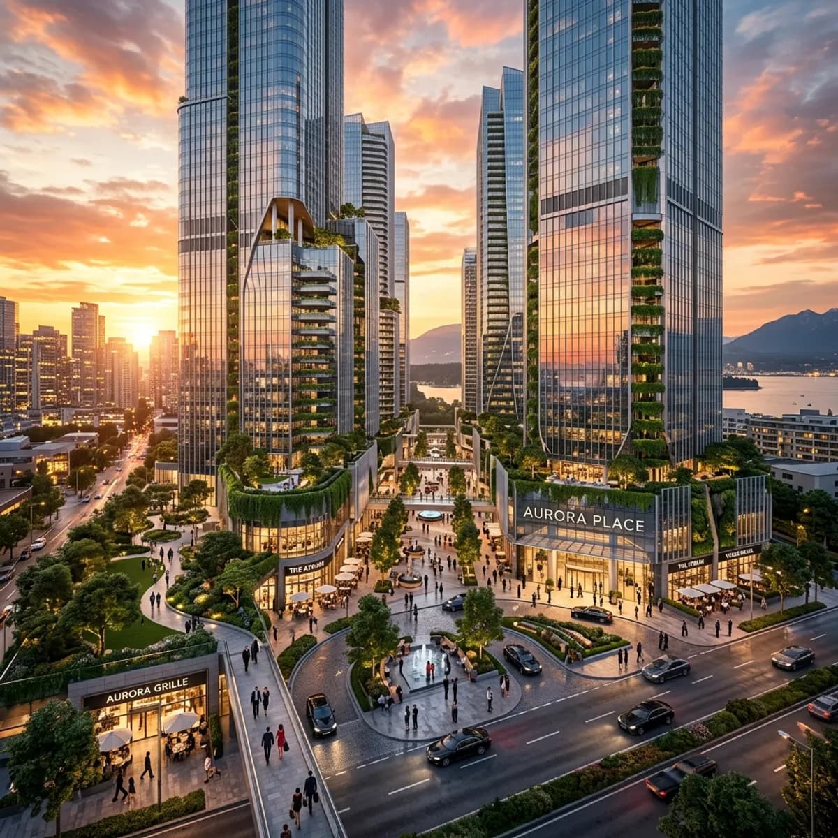
A rendering shows a building that does not yet exist. For developers and project managers it is often the only image available for marketing, financing and approvals over a period of many months. Expectations of the result are correspondingly high – and disappointment is correspondingly common when the process behind it has not been understood.
Because a rendering is not produced by loading a plan into a piece of software and pressing a button. Between the first document and the final image lie several clearly distinguishable stages of work, each of which demands its own decisions and brings its own sources of error. This article describes that path in full: from checking the source material through modelling, materials, lighting and computation to post-production and sign-off. The aim is that you, as the client, understand where your decisions take effect, which changes are cheap and which become expensive.
What a rendering technically is
A rendering is a synthetically generated image. Its basis is a three-dimensional model of the building and its surroundings, which is given material properties and light sources inside the computer. The rendering software then simulates how light in this virtual scene strikes surfaces, is reflected, refracted and absorbed, and calculates a colour value for every pixel from that.
This simulation is the decisive difference from a drawing or a collage. A rendering is not painted, it is computed. The software has no intent and no taste – it knows only geometry, material parameters and light. Everything that is to be visible in the image must exist beforehand as an object and be described with properties. A window handle missing from the model will not appear in the image. A material whose roughness value is set incorrectly will gleam like plastic even though it is meant to be natural stone.
The most practically important consequence follows from this property: the effort in a rendering arises predominantly before the actual computation. The image calculation itself is machine time and runs largely automatically. Modelling, material assignment and lighting are manual work, and they determine how long a project takes and how good it turns out.
Step 1: Check the source material and name the gaps
The first stage of work is not design but review. The client normally supplies planning documents: floor plans, sections, elevations and, in favourable cases, a landscaping plan and a construction specification. These documents are examined, checked for completeness and cross-referenced against one another.
Experience shows that three kinds of problem emerge in the process. First, contradictions between documents: the floor plan shows a door that does not exist in the section; the elevation shows four window bays, the floor plan five. Second, missing information: parapet heights, material specifications for facade and roof, window frame colours, the treatment of outdoor areas. Third, documents at the wrong stage of maturity: a preliminary design delivered as detailed design does not yet carry reliable dimensions.
The professional response to this is unspectacular but effective: all open points are collected and presented to the client as a list before modelling begins. Anyone who skips this round is making those decisions implicitly – and will have to correct them later, once the model already stands. Changing a facade colour is easy; changing a storey height after all materials have been assigned and the cameras set is not.
With existing buildings or extensions a further point arises: if the rendering is to show the new build in its existing context, reliable geometry of that context is needed. Old record drawings are often unsuitable for this because they depict the planned rather than the built state. In such cases a 3D survey of the existing building is the cheaper option compared with a rendering that later fails to match reality.
Step 2: Building the 3D model
The model is created from the reviewed documents. Walls, ceilings, openings, roof, stairs, balconies and parapets are rebuilt in three dimensions, as a rule dimensionally accurate to the plan. For interior renderings, floor build-ups, skirting, window reveals and fitted elements are added.
A widespread misconception holds that an existing BIM or CAD model makes this step unnecessary. That is only partly true. A planning model is optimised for planning purposes: it contains component information, layer build-ups and technical attributes that are irrelevant to image computation, while lacking many details that become visible in the image – joint patterns, profile cross-sections, handles, seals, transitions. An imported model saves the shell, but does not replace the detailing.
How finely the model is built depends on the framing. A bird's-eye view over a quarter needs no window handles. An interior shot two metres from the kitchen units does. The level of detail is therefore best defined per view rather than blanket-wise for the whole project. This is precisely where a large part of the cost difference between providers arises: anyone who models everything at high detail works uneconomically; anyone who models everything coarsely delivers images that fall apart at close range.
The surroundings belong to the model as well. Neighbouring buildings, terrain, street space, planting and ground surfaces determine the credibility of an exterior rendering at least as strongly as the building itself. A technically perfect house standing on a green plane in the middle of nowhere reads like a catalogue image rather than a place.
Step 3: Assigning materials
In the next step every surface receives its physical properties. Modern renderers work on a physically based basis: a material is not defined by a colour but by a series of parameters – base colour, roughness, metallic value, transparency, refractive index, and normal and displacement information for surface structure.
These parameters govern the impression of realism more strongly than the geometry does. The difference between a convincing rendering and one that looks cheap almost always lies in the material: concrete without roughness variation reads as grey cardboard, timber with an over-regular grain reads as laminate, glass without slight soiling and without frame depth reads as a hole in the wall.
One point is relevant for you as the client here: materials should correspond to the construction specification, not to whatever looks best in the picture. If vinyl is what the contract owes, oak parquet does not belong in the image – or it is expressly labelled as an optional upgrade. More on this in the section on legal considerations.
It is worth supplying available product information early: manufacturer designations for render, brick, roof tiles, window profiles and floor coverings. A material name is more precise than a colour description and saves a correction round.
Step 4: Camera and composition
Before lighting is set, the views are defined. A camera in a 3D scene has the same parameters as a real camera: position, direction of view, focal length, height above ground and orientation.
Camera height is the most frequently underestimated of these. Exterior shots at eye level – around 1.60 metres – show the building as a passer-by will see it. Shots from two or three metres already feel as though they float; bird's-eye views show massing and plot layout but lose the reference to human perception. Interior shots are usually placed at 1.20 to 1.50 metres; cameras set higher make rooms look smaller.
Focal length governs the sense of space. A wide angle shows a lot and makes rooms appear generous, but distorts proportions at the edges of the frame. An extreme wide angle is the classic way of making a twelve-square-metre kitchen-diner look like a loft. It works in the image and takes its revenge at the viewing.
The choice of views should therefore be made together with the client, ideally on the basis of simple, quickly computed preview images. That is the cheapest moment for changes: moving a camera costs minutes as long as no final image has been calculated.
Step 5: Setting the light
Lighting is the step in which a correct model becomes an image. For exterior shots the position of the sun is defined first – via location, date and time, so that shadows and light colour match the real situation. If you are showing a south-facing terrace, you should not depict it in a light that never occurs there.
The sky condition is added to this: a clear sky with hard shadows, light cloud with softer transitions, a low evening sun with warm light and long shadows. The choice has a considerable influence on the effect of the image and should suit the use. An office building in an evening mood is atmospheric, but says little about how it works during the day.
For interiors, artificial light is added: ceiling fittings, downlights, indirect lighting, floor lamps. Every light source has intensity, colour temperature and a distribution characteristic. An interior scene usually only becomes realistic once daylight and artificial light are combined – pure artificial light in an obvious daytime situation is a common giveaway of weak renderings.
Step 6: Furnishing and fit-out
For interior renderings the scene is furnished: furniture, textiles, lighting, plants, pictures, kitchen units, sanitary ware. Professional 3D model libraries are normally used for this, supplemented by purpose-built objects where a specific product is to be shown.
Furnishing serves two functions. First, it establishes scale: an empty room is hard for viewers to assess, whereas a sofa and a dining table make the size legible. Second, it conveys an address to a target group – a family apartment is furnished differently from a unit aimed at buy-to-let investors.
The most common mistake is overloading. Furniture placed more densely than the room could really accommodate produces exactly the disappointment one wanted to avoid. A good rule of thumb: the furnishing should be walkable. If there is not 40 centimetres between the sofa and the coffee table, the scale is wrong.
Step 7: Computation
Only now does the actual image calculation run. The renderer traces light rays through the scene and determines, for every pixel, which light reaches it from where. Because this method works statistically, the image emerges gradually: at first it is noisy, and it becomes cleaner as computing time increases.
Computing time depends on resolution, scene complexity, material properties and lighting situation. Interiors with indirect light take considerably longer than exteriors in direct sun, because the light has to be reflected several times before it reaches the camera. Large glazed areas, mirrored surfaces and vegetation raise the effort further.
Practically relevant for you: the computation step is the only one that can be accelerated with hardware. All the preceding steps are working time. Putting a deadline under pressure therefore does not shorten the computing time but the care taken over modelling and material work.
Step 8: Post-production
The computed raw image is finalised in image editing. Adjustments to contrast, colour mood and brightness distribution are usual, as are the insertion of sky and background, foreground vegetation, people and vehicles, and corrections to individual areas of the image.
This stage is legitimate and part of the craft – but it is also the point at which an image can depart from reality without the viewer noticing. A sky inserted that never appears in this orientation, a tree that does not stand on the neighbouring plot, a street without the bus stop that is really there: such interventions are quickly made and change what the image says.
Step 9: Correction rounds and sign-off
Two to three correction rounds are usual. A clear sequence makes economic sense: the view is signed off first, then model and materials, then light and mood, and finally details of post-production. Following this sequence means correcting early and cheaply.
Reversing it – only noticing on the finished image that the camera was too high – means paying for a complete recalculation. This is the most frequent cause of variations and delays in visualisation projects, and it is entirely avoidable.
Collect your correction requests in bundles as well. Five comments submitted individually create five processing cycles; the same five comments in one list create one.
Legal considerations: what a rendering promises
Renderings are non-binding illustrations – and that is usually how they are labelled in sales material. The note is correct and sensible, but it is not a blank cheque. An image makes a statement: if it shows a fireplace, it says there is a fireplace there.
The reliable rule is therefore that rendering and construction specification should describe the same building. Components such as balconies, roof terraces, dormers or bay windows only appear in the image if they are owed. Fixed fit-out is depicted in the specification actually contracted for. Outdoor areas correspond to the landscaping plan. Furniture is recognisably decoration and therefore unproblematic.
Anything going beyond that belongs labelled. A caption such as "shown with optional upgrades, not included in the purchase price" costs one line and prevents an argument at handover. It is also a sales argument, because it opens a conversation about upgrades instead of preparing a disappointment.
Second point: usage rights. The rendering is a work in which its creator holds rights. What you receive is a grant of usage rights to a defined extent. Clarify in writing before commissioning: for which project, in which media, for what duration, whether you may edit the images and whether you may pass them on to sales partners, agents or the press. The last point is the one most often overlooked, and it surfaces precisely when things are urgent.
This section is a general orientation drawn from project practice and does not replace legal advice. For specific questions on purchase contracts or licence agreements, a lawyer is the right route.
Limits and typical mistakes
Renderings can do a great deal, but not everything. You should know these limits before commissioning.
A rendering is only as good as the design. Where the design is unfinished, images are produced that pre-empt decisions which have not yet been made. If the design changes, the image is wrong. At very early project stages a deliberately abstracted image is more honest than a photorealistic one.
Photorealism is not always the goal. An image that looks like a photograph will also be read like one – as a depiction of something that exists. For competition entries or early marketing stages, a recognisably illustrative depiction is often the better choice.
Colours are not binding. What appears correct on a calibrated monitor looks different on a smartphone or in print. Choosing facade colours from an image regularly leads to disappointment; sample areas exist for that purpose.
Vegetation does not age with the building. Renderings usually show planting in a mature state. The real condition at handover is a different one. Failing to communicate this produces queries.
Later floor plan changes are expensive. If the unit layout is altered after the model has been signed off, the work on furnishing, lighting and materials in the affected areas is lost.
Too many views are a waste. Three well-chosen images have more effect than ten arbitrary ones. What usually makes sense is one exterior view at eye level, one overview of the massing and one or two interiors of the most important unit types.
Renderings do not replace photographs of the finished building. Once construction is complete, marketing should switch to real photographs. Continuing to market with renderings when the building stands looks implausible to prospective buyers.
What you as the client can contribute
The effort on your side is manageable, but it has a large influence on quality and adherence to deadlines.
Supply complete and current planning documents at the latest approved stage, ideally as a CAD file plus a PDF. Name materials with manufacturer or colour designation. State which target group the images are meant to address. Define the output formats – print requires considerably higher resolutions than a portal listing, and resolution is set before computation, not afterwards.
And nominate one person with authority to decide. Correction rounds in which contradictory feedback from different departments converges are the most reliable way of drawing a project out.
Conclusion
A rendering is created in a clear sequence: check the source material, build the model, assign materials, set the cameras, define the light, furnish, compute, post-process, correct. The bulk of the effort lies before computation, and the bulk of the quality is decided in material and light.
Two practical consequences follow for clients. First, make decisions early, particularly on views and design maturity – late changes are disproportionately expensive. Second, align the image with the construction specification. A rendering that shows more than is contractually owed buys attention and pays for it with friction at handover.
If you would like a project visualised, you will find the scope of services under property rendering.