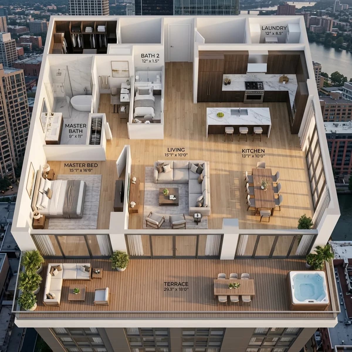
The classic 2D floor plan is a technical drawing. It is made for people who have learned to read hatching, symbols and dimension strings. For architects, tradespeople and surveyors it is the most precise tool available – for prospective buyers it is often an obstacle.
The 3D floor plan removes that obstacle. It shows the same layout as a spatial depiction with visible wall heights, furniture and floor coverings, usually from a bird's-eye view without the ceiling. What requires interpretation in the 2D drawing is directly legible here: how the rooms connect, where there is space for what, how long the hallway really is.
This article describes how a 3D floor plan is created, what source material it needs, which forms of depiction exist – and where its limits lie.
What a 3D floor plan is
A 3D floor plan is a three-dimensional depiction of one storey, usually cut above the window sill and below the ceiling. The viewer looks into the flat from an angle above. Walls appear with visible height, floors are shown with their coverings, rooms are furnished.
It is therefore neither a technical drawing nor a rendering but something in between: it retains the dimensional accuracy and completeness of a floor plan and adds the immediacy of a spatial depiction. That is precisely where its function in marketing lies.
It should be distinguished from interior visualisation: a rendering shows a room at eye level, with full wall height, lighting and atmosphere. The 3D floor plan shows the flat as a whole and gives up the sense of enclosure in return. The two complement each other; they do not replace one another.
Step 1: Checking the source material
Review of the source documents comes first. Usable, in descending order of quality: a CAD file of the floor plan, a dimensioned PDF, an undimensioned but scaled drawing with a scale statement, an on-site survey, a sketch with measurements.
The most common case in practice is a PDF from the building application or the sales file. That is workable but demands care: the drawing is imported to scale and calibrated against the dimensions shown. Where the stated dimension and the drawn length do not agree – which happens regularly with drawings that have been copied or rescaled several times – the stated dimension governs, not the drawing.
Alongside the geometry, information is needed that a 2D drawing does not always contain: room height, window sill heights, door opening directions, the position of entrances and stairs, and – where there are several levels – how the storeys relate to one another.
Existing buildings without reliable drawings are a special case. Where available documents depict the planned rather than the built state, the 3D floor plan becomes precisely accurate on a false basis. A survey is the cheaper route here; for larger or irregular properties a 3D survey of the existing building provides the more reliable basis.
Step 2: Cleaning up the drawing
Before modelling begins, the drawing is read and cleaned up. Technical drawings contain a great deal of information that is neither needed nor depictable in a 3D floor plan: dimension strings, grid lines, section lines, level markers, component numbers, legends, building services symbols.
Inconsistencies are resolved at the same time. Typical ones are: wall thicknesses depicted inconsistently across the drawing; doors with no recognisable opening direction; rooms without designation; openings whose height is not stated. These points are collected and put to the client before building begins – later corrections take more effort, because by then the model is already furnished and textured.
Step 3: Building walls, openings and levels
The model is created from the cleaned-up plan. Walls are extruded at their real thickness to the defined cut height, openings for doors and windows are cut out, and reveal depths are taken into account.
The cut height is a deliberate design decision. Cut too low, windows are lost and the walls read like a cardboard model. Cut too high, the walls conceal parts of the furnishing and the rooms become hard to see into from above. The usual height is one at which window sills and door openings remain recognisable.
Elements permanently belonging to the building are added: stairs with the correct number of risers, landings, plinths, niches, chimneys, sloping ceilings, columns. Sloping ceilings matter in particular, because they limit usable area – a loft storey without depicted slopes makes a false statement about usability.
Step 4: Floors, materials and colour world
Every room receives its floor covering: parquet, tiles, vinyl, carpet, screed. The covering serves two functions. First, it makes room boundaries legible without labelling – the change from parquet to tiles marks the bathroom or kitchen boundary at a glance. Second, it conveys a sense of quality.
The substantive link matters: the covering depicted should correspond to the actual or the contractually owed one. A 3D floor plan showing oak parquet for a flat that will be laid with vinyl creates the same expectation gap as an over-generous rendering.
Restraint applies to the colour world. The 3D floor plan is meant to explain the structure of the flat, not to compete with it. Colours that are too strong, too many changes of material and dominant patterns hinder exactly the reading the depiction is supposed to make easier.
Step 5: Furnishing
Furnishing is the step that translates area into use. It answers the questions a 2D drawing leaves open: does a double bed fit this bedroom? Where does the dining table go? Is there working space beside the kitchen units? How much of the living room is circulation?
The decisive quality criterion is dimensional accuracy. Furniture is inserted at real dimensions: a double bed at 1.60 by 2.00 metres, a dining table for four at around 1.20 by 0.80 metres, a sofa at a realistic depth. Circulation routes are kept clear – around 80 centimetres of passing width, adequate distance in front of wardrobes and kitchen units.
A furnished 3D floor plan that observes these rules is a powerful marketing instrument, because it pre-empts a question every prospective buyer asks. One that breaks them is a risk: anyone who sees a double bed plus wardrobe plus desk depicted in a nine-square-metre room, and discovers at the viewing that two of those pieces fit, will mistrust every other statement afterwards.
The furnishing should also suit the target group: a family flat, an investor unit, a student apartment and a penthouse each call for a different furnishing logic.
Step 6: Labelling and area figures
A 3D floor plan without labelling is attractive but incomplete. Usual and useful are: room designations, room areas in square metres, the total area, a north indication and, where relevant, the storey designation.
One clarification matters with area figures. Different bases of calculation exist – living area under the applicable regulations, usable area, gross floor area under the relevant standard – and they lead to different numbers, particularly with sloping ceilings, balconies and terraces. The area depicted in the plan arises from the geometry and is not automatically the contractually relevant living area.
The clean approach: take area figures from an existing, reliable calculation and state the basis of that calculation. Where none exists, label the figure as approximate. A square-metre figure in a listing is read by prospective buyers as an undertaking.
Step 7: View, lighting and computation
The viewing angle is defined. Two variants are usual: the perspective view from an angle above, which feels spatial but reduces distant areas in size, and the isometric or axonometric depiction, in which all areas appear at the same scale and the flat therefore remains easier to compare.
For residential floor plans the slightly perspective view has become established because it feels more accessible. For complex or large layouts the isometric variant is often the better choice, because it disadvantages no area.
The lighting is deliberately neutral: even, soft light without hard shadows, so that all areas are equally legible. A dramatically lit 3D floor plan looks more elaborate at first glance but makes the structure harder to grasp.
The image is then computed and post-processed – contrast, colour balance, labelling and, where applicable, a logo and scale statement.
Variants of depiction
Besides the classic furnished 3D floor plan, several variants are common.
The unfurnished depiction shows only the built structure with floor coverings. It is neutral, suits technical purposes and properties where the use is to remain open.
The sectional perspective plan does not cut horizontally but shows the flat with full walls from one side. It feels more spatial but conceals areas.
The stacked storey view depicts several storeys offset above one another and makes the vertical organisation of a house comprehensible. It is useful for terraced houses and maisonettes.
The building section shows the whole house cut through and is useful in apartment blocks for explaining where a single flat sits within the building.
Limits and typical mistakes
A 3D floor plan does not replace a technical drawing. It is unsuitable for tradespeople, structural engineers, building applications or surveys. It contains no complete dimensioning, no component build-ups and no technical layers. Using it as a basis for design work means working from a marketing document.
The accuracy is that of the source drawing. A 3D floor plan produced from a wrong 2D drawing is just as wrong – only more convincingly depicted. The vividness increases credibility, not correctness.
Furnishing distorts perception when it is not to scale. Undersized furniture makes rooms look larger. This error is particularly effective in 3D floor plans, because the viewer uses the furniture as a reference for scale.
Rooms appear differently depending on the view. In a perspective depiction, distant rooms appear smaller. In a flat with an uneven distribution of rooms this can shift perception.
Height information is largely absent. A cut above the sill shows no room height. A flat with 2.30 metres and one with 3.20 metres look almost identical in a 3D floor plan, yet differ considerably in reality.
Loft storeys are critical. If sloping ceilings are not depicted, a completely false impression of the usable area arises. In loft flats the slope belongs in the image.
Too much decoration distracts. The purpose is orientation. Elaborately decorated plans with many small objects look valuable but make the plan harder to read.
The area figure is read as an undertaking. Approximate values without a label are one of the most frequent causes of later queries.
When a 3D floor plan is worthwhile
It is particularly effective for properties with a layout that needs explaining, for new-build projects with several unit types, for loft flats and maisonettes with a complex sequence of rooms, and for larger flats whose structure is hard to grasp from a 2D drawing.
It adds less for very simple, small layouts with two or three rooms – there the 2D drawing is understood quickly enough – and for properties where the condition rather than the structure is the selling point.
The combination makes sense: the 2D drawing for the technical level, the 3D floor plan for marketing. Together they answer more questions than either does alone.
Conclusion
A 3D floor plan is created in a clear sequence: check and calibrate the source material, clean up the drawing, build walls and openings, assign floors and materials, furnish to scale, label and add areas, define view and lighting, compute and finish.
Quality is decided at two points: the reliability of the source data and the dimensional accuracy of the furnishing. A 3D floor plan that observes both answers prospective buyers' questions before the viewing. One that does not generates appointments that end in the living room, because the bedroom is smaller than expected.
You will find the scope of services under 2D and 3D floor plans.