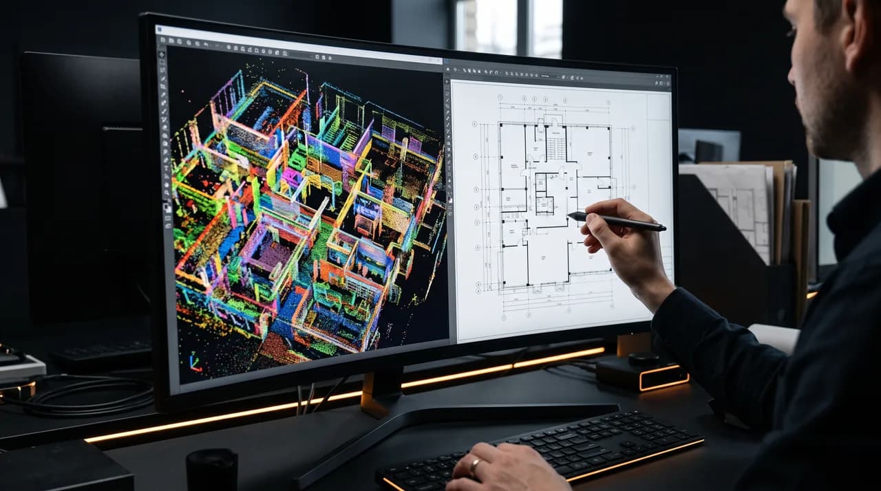
Anyone who has seen a raw point cloud for the first time knows the moment of confusion: millions of coloured dots floating in space, technically impressive, but not something you can hand to a contractor or attach to a permit application. The gap between "we scanned the building" and "here is your CAD plan" is where the real work happens, and it is a gap that surprises a lot of clients. They assume the scanner does the drawing. It does not. The scanner captures geometry; a structured pipeline of software and human judgement turns that geometry into a plan someone can actually build from.
This article walks through that pipeline stage by stage, from what a point cloud technically contains, through alignment and cleanup, to the modelling decisions that determine whether a plan is fit for a renovation permit, a facility management system, or a marketing floor plan. Understanding these steps helps architects, developers and facility managers brief their surveying partner correctly, interpret quotes and timelines, and know what to check before signing off on a deliverable.
What a Point Cloud Actually Contains
A point cloud is the direct output of a laser scanner: a dense collection of individual measurement points, each with an X, Y and Z coordinate relative to the scanner's position, plus typically an intensity value and, if the scanner has a built-in camera, an RGB colour value. A single interior scan position in a mid-sized room can easily produce tens of millions of points. Multiply that across a full building with dozens of scan positions and you are working with datasets in the range of several gigabytes to well over a hundred gigabytes for a large commercial property.
What the point cloud does not contain is any concept of "wall", "door", "window" or "room". It is pure geometry — a three-dimensional snapshot of every surface the laser hit, including furniture, plants, people who happened to walk through the scan, reflections off glass, and shadows where the beam could not reach behind an obstruction. A radiator in front of a wall is recorded as a radiator, not as "a wall with a radiator in front of it". Extracting the building envelope from that raw geometry is precisely the task that the rest of this workflow addresses, and it is why point cloud data and CAD data are fundamentally different products even though one derives from the other.
It is also worth understanding that scan quality varies with material and lighting. Dark, matte, or highly reflective surfaces return weaker or distorted signals; glass and mirrors can produce phantom points behind the actual surface. A competent scanning team already anticipates these issues on site by adjusting scan positions and density, but some artefacts only become visible once the data is examined in processing software, which is why the workflow includes dedicated cleanup stages before any drawing work begins.
Registration: Aligning Multiple Scan Positions
No single scan position can capture an entire building — line of sight is blocked by walls, furniture, and the scanner itself. A typical residential floor might need eight to fifteen scan positions; a multi-storey commercial building can require well over a hundred. Each of these positions produces its own point cloud in its own local coordinate system, and the first major processing step, called registration, is the process of stitching all of these individual clouds into a single, consistent coordinate system.
Registration relies on overlapping geometry between adjacent scans, on visible targets (spheres or checkerboard markers placed in the space before scanning), or on a combination of both. Modern scanning software can perform much of this automatically by recognising common features — a distinctive corner, a doorframe, a piece of furniture — across neighbouring scans and calculating the transformation needed to align them. The software reports a registration error, usually in millimetres, indicating how well the scans agree with each other at their overlap zones. For most architectural and construction documentation, this error should stay within a few millimetres; anything larger signals a problem that needs to be resolved before proceeding, whether that is insufficient overlap, moved objects between scans, or drift from a long chain of registrations without closing loops back to a reference point.
Getting registration right matters enormously for everything downstream. An error introduced at this stage propagates through every subsequent measurement, and it is far cheaper to catch and correct it here — sometimes simply by adding a supplementary scan — than to discover a systematic offset after a CAD plan has already been drawn and delivered. This is one of several reasons experienced surveying teams plan scan positions deliberately on site rather than scanning opportunistically and hoping registration software can sort it out afterwards.
Noise Reduction and Outlier Cleanup
Once the individual scans are registered into one unified cloud, the dataset still contains a considerable amount of noise: stray points from dust or moving objects during the scan, ghost points from reflective or transparent surfaces, and general measurement scatter around every real surface. Left untreated, this noise makes it harder for both automated detection algorithms and human operators to interpret the true geometry underneath.
Cleanup at this stage typically combines automated filtering with manual review. Statistical outlier removal algorithms flag points that sit unusually far from their neighbours and remove them in bulk. Density-based filters can strip out sparse, scattered points that do not belong to any coherent surface. But automated filtering has to be applied carefully — too aggressive a filter can delete thin but genuine features such as railings, cables, or fine architectural mouldings along with the actual noise. This is where an operator's judgement earns its keep: knowing which anomalies are scanning artefacts and which are real (if awkward) building elements is not something a generic filter can reliably decide on its own.
Beyond noise removal, this stage also involves decluttering: removing points that belong to furniture, temporary fixtures, vehicles, or people, so that what remains represents the fixed building fabric relevant to the deliverable. Depending on the project, some of this "clutter" is actually wanted — a facility manager cataloguing existing equipment may want furniture and installations preserved in the model rather than stripped out — so the cleanup step is guided by the intended use of the final plan, not applied as a one-size-fits-all default.
Detecting Walls and Openings: Automation Meets Interpretation
With a clean, registered point cloud in hand, the next task is to identify the actual architectural elements: walls, their thickness, floors, ceilings, and openings such as doors and windows. This is where automation delivers real time savings, and also where its limits become clearest.
Automated wall-detection algorithms typically slice the point cloud into horizontal sections at a chosen height and look for dense, linear clusters of points that indicate a flat vertical surface — a wall. Where two such planes run roughly parallel to each other at a plausible wall thickness, the software can infer a wall segment automatically, and modern scan-to-BIM plugins can generate a rough wall layout for an entire floor in minutes rather than the hours it would take to trace by hand. Openings are detected as gaps in an otherwise continuous wall plane, often cross-referenced against a second horizontal slice to confirm the gap continues from floor to head height, distinguishing a door opening from, say, a recessed shelf.
However, this automated pass is a starting point, not a finished plan. Algorithms routinely misread curved walls, walls interrupted by built-in furniture, partial-height partitions, splayed reveals, or areas where scan coverage was thin and the point density drops. A door left open during scanning may register as a wide opening rather than a door with a frame; a stud wall with a plastered finish can be indistinguishable in point data from a load-bearing masonry wall, a distinction that matters enormously for renovation planning. This is precisely where a trained CAD operator reviews every automatically generated segment against the underlying point cloud and the site context, correcting misreads, adding elements the algorithm missed, and applying construction knowledge that the software has no way to infer from geometry alone — for instance, recognising that a gap in the data is a scanning shadow behind a cupboard rather than an actual opening in the wall.
Choosing the Right Level of Detail for the Intended Use
One of the most consequential decisions in the entire workflow is also one clients rarely think to specify up front: how much detail does the final plan actually need? A CAD plan intended for a marketing floor plan on a property listing needs accurate room shapes and dimensions but no information about wall construction, services, or millimetre-level moulding profiles. A plan feeding into a renovation permit application needs correct wall thicknesses, window and door positions, and often room areas calculated to a defined standard. A plan destined for a facility management system or a BIM model for building services coordination needs far more: pipe runs, ceiling voids, structural elements, and often a full 3D model rather than a flat 2D drawing.
Industry frameworks describe this as Level of Detail or Level of Development, and while formal LOD classifications originate in BIM standards, the underlying principle applies just as well to simpler 2D CAD deliverables. Modelling everything to the highest possible detail regardless of purpose is not a sign of thoroughness — it is wasted effort that inflates turnaround time and cost without adding value to a client who only needed a clean floor plan. Conversely, under-specifying detail for a project that later needs structural information means expensive re-surveying down the line.
Getting this right depends on a clear conversation before scanning even begins: what is the plan for, who will use it, what format does it need to be delivered in, and what tolerances matter. A good surveying partner asks these questions explicitly rather than defaulting to a fixed template, because the same point cloud can be turned into wildly different deliverables depending on the answer, and re-scanning a building because the wrong level of detail was assumed is a cost nobody wants to absorb.
The Software Landscape Behind the Pipeline
The journey from point cloud to CAD plan typically passes through several distinct categories of software, each suited to a different stage of the process. Scan registration and initial cloud processing happens in dedicated point cloud software built to handle the sheer data volume efficiently — these tools can load, align, and visually inspect datasets of hundreds of millions of points without grinding to a halt, something general-purpose CAD software is not built to do.
Once the cloud is clean and registered, it is imported into a scan-to-CAD or scan-to-BIM environment, often as a plugin running inside standard CAD or BIM authoring software. This is where the automated wall and opening detection happens, and where the operator traces, corrects, and completes the drawing. The point cloud typically remains visible as a background reference layer throughout this stage, so every line drawn can be checked directly against the underlying measured data rather than against an approximation.
Finally, the finished drawing is exported into the format the client actually needs — a 2D DWG or DXF plan, a 3D BIM model in IFC format, or a PDF for straightforward review and sign-off. Each export step carries its own considerations: layer naming conventions, unit systems, whether furniture and fixtures are included as separate layers, and whether the drawing needs to match an existing office CAD standard for consistency with prior documentation of the same building. None of this is exotic technology, but coordinating it correctly across formats and standards is a meaningful part of what a professional surveying partner is actually delivering.
Quality Control and Verification
A CAD plan is only as trustworthy as the checks performed on it before delivery, and quality control at this stage typically works on two levels. The first is geometric verification: comparing key dimensions in the finished plan directly against the point cloud, and ideally against a handful of independent physical measurements taken on site, to confirm the drawing matches reality within the agreed tolerance. Any discrepancy larger than that tolerance gets traced back through the pipeline — sometimes to a registration issue, sometimes to a misread wall, sometimes to a genuine as-built irregularity that simply needs to be represented correctly rather than "corrected" to look tidier than the real building.
The second level is consistency and completeness review: checking that every room is closed and labelled, that door and window symbols match their actual swing direction and opening type, that room areas are calculated according to the standard the client specified, and that the drawing follows the agreed layer structure and naming conventions. This is typically done by a second reviewer rather than the operator who produced the drawing, precisely because a fresh set of eyes catches errors the original modeller has become blind to after hours of close work on the same file.
For projects with tighter tolerance requirements — historic building documentation, structural assessments, or plans that will inform load calculations — additional spot checks against independent survey control points may be built into the QA process. The goal throughout is the same: the client should never be the first person to discover that a dimension is wrong.
Turnaround Times and Why Skilled Operators Remain Essential
Turnaround expectations depend heavily on building size and the level of detail requested, but as a general guide, a straightforward residential floor plan from an already-scanned property can often be turned around within a few working days, while a larger commercial building with a full BIM deliverable and services coordination can take several weeks. Registration and cleanup, being partly automated, tend to be the faster stages; the wall and opening review, quality control, and any client revision rounds are where most of the calendar time is actually spent, precisely because that is where human expertise is doing the heavy lifting.
This brings us to a point worth stating plainly: despite genuine and continuing advances in automated point-cloud-to-CAD software, skilled CAD operators are not a legacy step waiting to be automated away — they are the reason the deliverable is trustworthy. Automation is excellent at proposing a first draft quickly; it is not good at recognising context, resolving ambiguity, or applying the kind of building knowledge that comes from having reviewed hundreds of real, imperfect buildings. A wall that looks identical to an algorithm can mean structural or non-structural depending on context an experienced operator recognises instantly and software does not.
The realistic picture, and the one clients are best served by understanding, is a hybrid workflow: automation handles the repetitive geometric heavy lifting, and trained operators apply judgement, catch what the algorithms miss, and take responsibility for the accuracy of the final drawing. That combination is what actually produces a plan an architect can design against, a facility manager can rely on, and a contractor can build from without surprises on site.
Conclusion
Turning a raw point cloud into a usable CAD plan is a structured process, not a single automated step: it moves from understanding what the scanner actually captured, through registering multiple scan positions into one coherent dataset, cleaning noise without discarding genuine detail, detecting walls and openings with a combination of algorithms and human review, and matching the level of detail to the plan's real purpose. The software involved spans dedicated point-cloud tools, scan-to-CAD environments, and standard CAD or BIM authoring platforms, each playing a specific role in the pipeline, all of it underpinned by quality control that checks the finished drawing against the measured reality it is meant to represent.
For architects, developers, and facility managers commissioning this work, the practical takeaway is to be explicit up front about what the plan needs to do — permit submission, renovation planning, facility management, marketing — since that decision shapes every stage downstream and directly affects cost and turnaround. And despite how much of the pipeline can now be automated, the accuracy and reliability of the final drawing still rests on experienced operators who know how to read a building through its point cloud, not just through an algorithm's first guess.