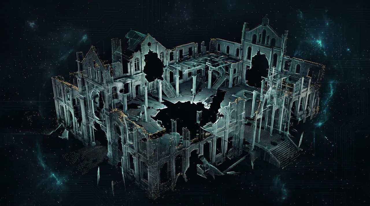
At first glance, a point cloud is almost always impressive. Millions of measurement points, a walkable 3D model of the building, fine details right down to the screw on the door. The client sees the colorized view, rotates the model on screen, and is convinced: everything here has been captured. That is precisely where the pitfall lies. A point cloud rarely looks incomplete. It looks complete – until someone tries to work with it.
The gaps in a poorly captured point cloud hide behind furniture, in ceiling voids, on glass facades, and in corners that no one could see from the scanning position. They do not show up at handover, but weeks later – when the architect wants to derive a floor plan, the specialist planner wants to route a service run, or the facility manager wants to calculate an area for leasing. At that moment, an elegant 3D view becomes a dataset full of holes, and the question suddenly becomes: who goes back on site?
This article describes where point clouds typically become incomplete, why these gaps become visible so late, and how they can be avoided through sound planning and control in the field. It is aimed at everyone who has to work with the results – architects, specialist planners, and building management – and who therefore has an interest in getting the data foundation right before the crew has driven off again.
What “complete” actually means for a point cloud
A laser scanner only measures what it directly sees. It emits a beam, measures the travel time or phase shift of the reflected light, and calculates a point in space from it. Anything standing between the scanner and a surface casts a shadow – just like a light source. No information is created behind that shadow. The space behind it simply does not exist in the point cloud, and the model shows a blank spot there, not an error message.
Completeness therefore does not mean that there are many points somewhere. It means that every surface relevant to later use was hit from at least one – and preferably several – positions. A wall grazed only from a very shallow angle yields few, noisy points. For a nice visualization, that is often enough. For a reliable edge, where a planner takes the line of a wall, it is not.
From this follows an uncomfortable truth: whether a point cloud is complete cannot be judged from the overall impression, but only with the specific purpose in mind. One and the same capture may be entirely sufficient for a rough as-built documentation and unusable for millimeter-accurate MEP planning. Anyone who does not clarify the intended use in advance cannot meaningfully check completeness in the field – and only notices at the desk that something is missing.
The classic: shadows behind furniture and fixtures
The most common cause of gaps is shadowing from objects in the room. A cabinet, a shelf, a machine, a radiator, boxes stacked in a still-active warehouse – each of these blocks the laser beam and leaves a data-free area behind it. If the scanner stands in only one spot in the room, the entire far side of every piece of furniture remains uncaptured. What sounds harmless quickly adds up to considerable missing areas in a furnished office or a running production floor.
It becomes particularly annoying at exactly the spots that are needed later. The wall niche behind the filing cabinet where a new line is supposed to go. The corner behind the workbench where a support sits. The base of a wall hidden by a continuous sideboard. The scanner saw the room, the model looks closed – but at exactly the planning-relevant edge the information is missing, because a piece of furniture was in the way.
The countermeasure is conceptually simple and, in practice, the most common reason for extra effort: more positions. Every additional scan position looks into the room from a different angle and fills the shadows of the previous one. Where one position sees a cabinet from the front, the next looks in behind it from the side. This redundancy is not a luxury, but the actual prerequisite for completeness. Anyone who saves on positions to finish faster is saving at exactly this point – and shifting the cost to later post-processing or a second visit.
Upward and into the gaps: ceilings, shafts, plant rooms
A second, often underestimated area comprises the zones that are hard to see from the floor. Suspended ceilings with the void above them, service shafts, raised floors, cramped plant rooms, angular lift overrun spaces. The scanner stands on its tripod at normal height and dutifully measures the room – but the ceiling void, where the actual building services run, stays closed and thus uncaptured. For a pure room capture, that does not matter. For a refurbishment or MEP planning, it is the area of greatest interest.
Plant rooms are a chapter of their own. They are cramped, crammed with units, pipes, and distribution panels, and it is precisely this density that produces a multitude of small shadows. Behind every pipe run, every distribution cabinet, every unit lies a shadow. A single position in the center of the room delivers a point cloud here that looks like Swiss cheese. Such rooms need disproportionately many positions relative to their floor area – a fact that tends to be overlooked in a flat-rate scan plan.
Anyone who wants to include such areas must state it in advance and plan for it in the survey. Ceiling voids require opened access hatches and, in part, scans from within the void itself. Shafts call for captures from several floors so that the vertical is recorded continuously. This is not incidental effort, but a deliberate decision that shapes the scope of the capture. If it is not made, the result is a point cloud that ends wherever things get interesting.
When the material won’t cooperate: glass, mirrors, glossy and black surfaces
Some gaps have nothing to do with position, but with the physics of the surface. A laser scanner needs diffuse reflection in order to measure: the beam hits, scatters back, the sensor receives it. With certain materials, this does not work reliably. Glass lets most of the beam pass through, so the scanner measures what lies behind it – or nothing at all. Mirrors and high-gloss surfaces throw the beam off in a completely different direction, like a ray of light, which leads to ghost points behind the mirror plane.
Dark and black surfaces are a problem of their own. They absorb a large part of the laser light, so little signal comes back. A matte black wall, a dark floor covering, a black server cabinet – all of these deliver thin, noisy, or no points at all, especially at greater distances or at a shallow angle. Wet and highly glossy floors also fall into this category. The result is holes at spots where a surface is visibly present but no data lies.
These material-related gaps cannot be fixed by merely repositioning the scanner; they require deliberate technique. Moving closer, choosing a steeper angle, approaching glass surfaces from several directions, additionally documenting critical areas photographically or by hand measurement. An experienced operator recognizes problematic materials on site and reacts – a purely schematic working-through of the positions does not. Anyone who knows that glazing or a mirror wall will later be planning-relevant should raise it beforehand, so that the work in the field is carried out accordingly.
Drift: when the pieces don’t fit together cleanly
A point cloud almost never consists of a single scan, but of many individual captures assembled into an overall model. This assembling is called registration. Each position must be precisely aligned relative to the others. If this succeeds only imprecisely, drift arises: the errors of the individual links add up over the distance, and at the end of a long run – for instance in a corridor building or across several floors – the model lies several centimeters off from reality.
Drift is especially insidious because it is locally invisible. In each individual room, the cloud looks clean and closed. Only over the total length does the deviation become visible, and then often only if someone actively re-measures. A wall that appears parallel in the model is in truth slightly tilted. Two floors that should line up cleanly above each other are shifted relative to one another. Formally, the cloud is complete – but the geometric foundation is wrong, and every dimension chain derived from it inherits the error.
Against drift, an overlapping capture strategy helps and, on demanding projects, a superordinate control. Sufficient overlap between adjacent positions gives the registration enough common features. On larger or angular objects, a network of controlled reference points or a total-station survey secures the overall structure, so that the errors do not build up unchecked. Without this control, accuracy over larger distances remains a hope, not a commitment – and that can hardly be repaired after the fact on the finished dataset.
Why the gaps only surface at the desk
The real damage does not come from the gap itself, but from the moment it is discovered. In the field, the crew is focused on the workflow: work through positions, relocate, move on. The raw point cloud is often shown on the device only as a rough preview. Whether there really is data behind the cabinet in room 214 cannot be seen in this view. When the capture is finished and all positions have a green checkmark, a feeling of being done sets in.
The gap only reveals itself in further processing. The processor cuts a section through the model to derive a floor plan, and the section line runs into empty space because there are no points at the decisive spot. The specialist planner wants to take a clear height and finds no ceiling points. The facility manager calculates a lettable area and discovers that a wall behind a fixture is not defined. In all these cases, the capture was made weeks ago, the object possibly rebuilt, cleared, or back in operation – and the missing information can no longer simply be made up.
This is exactly where the economic heart of the topic lies. A gap detected in the field costs ten minutes of repositioning the scanner. The same gap, discovered at the desk, costs a renewed visit, coordination with the user, access, waiting time in the project, and, in the worst case, a plan built on false assumptions. The difference between a good and a bad capture is therefore rarely the technology – it is the question of whether someone checks completeness while there is still something that can be changed.
How gaps can be avoided: planning, positions, control
The first lever is scan planning before the visit. Anyone who knows what the data will be used for can determine which areas must be captured at what accuracy. A floor plan places different demands than an MEP as-built survey, a facade different from a cramped plant room. From this clarification of the goal follows the density of positions, the handling of ceilings and shafts, and the question of whether furniture or hatches need to be opened. A capture without this clarification is a blind flight that may turn out well by chance – or not.
The second lever is discipline in the field: enough positions, deliberately placed, with sufficient overlap, and no shortcuts in cluttered or shadowed areas. A furnished room needs more positions than an empty one, a plant room more than an office. Anyone who takes redundancy seriously would rather set one position too many than one too few – because the extra position in the field is always cheaper than post-processing the hole. This attitude distinguishes a careful capture from a hurried one more clearly than any piece of equipment.
The third lever is the completeness check before leaving the object. Even on site, the preliminary registration can be checked and the cloud compared against the critical requirements: are the planning-relevant edges hit? Is there data behind the fixtures? Does the overall structure fit together? Such a check uncovers gaps while the remedy is still trivial. And if it turns out that an area cannot be captured cleanly under the given conditions, a deliberately planned second appointment is more honest and, in the end, cheaper than a dataset whose gaps the next processor is the first to find.
Conclusion
An incomplete point cloud is rarely a spectacular error. It is a quiet defect that hides behind a convincing 3D view and only becomes loud when someone seriously wants to work with the data. Shadows behind furniture, unseen ceiling voids and plant rooms, material-related holes on glass, mirrors, and dark surfaces, and drift from imprecise registration – all of this creates blank spots that cost ten minutes in the field and a whole day’s visit at the desk.
The difference between a reliable capture and a full-of-holes one lies not in the scanner, but in three things: scan planning that starts from the intended use; enough deliberately placed positions with genuine redundancy; and a completeness check that takes place while there is still something that can be changed. Anyone who takes these three points seriously gets a point cloud that not only looks complete, but actually is complete where it counts.
For architects, specialist planners, and building management, this means one thing above all: clarify the purpose of the capture as early and as concretely as possible, and insist on a check before leaving the object. The decisive question is not how many millions of points are ultimately delivered – but whether the few edges, heights, and areas you really need are cleanly contained within them.