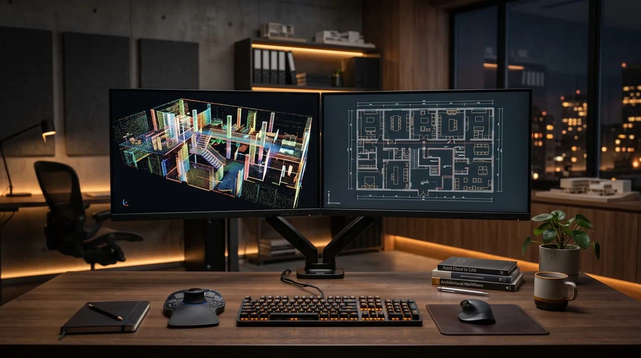
It is a situation we encounter time and again at FotoEstate: an architecture firm, a facility management team, or a building owner calls and says, in effect: "We already had the building scanned into a point cloud – so why can't we get a proper CAD plan out of it?" Sometimes the point cloud has been sitting on a server for months, several hundred gigabytes in size, technically captured without a flaw. And yet it turns out to be surprisingly useless in day-to-day planning work.
The reason is rarely poor surveying technology. Modern laser scanners capture millions of points with millimetre precision. The problem lies somewhere else entirely – namely in the widespread assumption that a point cloud is already something like a plan, just in 3D. It is not. A point cloud is raw geometry without any meaning. It contains no walls, no doors, no storeys, and no building components – nothing but the coordinates of surface points.
In this article we explain why the leap from a point cloud to a usable CAD plan requires genuine professional interpretation, which quality problems typically arise in the process, why fully automated scan-to-CAD regularly fails on real existing buildings – and what exactly you should tender and specify in order to end up with a plan you can actually work with.
A Point Cloud Is Raw Geometry – Not a Finished Plan
Imagine standing in a room and using a laser pointer to mark, one after another, millions of individual points on walls, floors, ceilings, window sills, radiators, and cable trunking. Each point is assigned an exact X, Y, and Z coordinate. That is precisely what a point cloud is: a gigantic list of spatial positions, often supplemented by colour and intensity values. What this list does not contain is any statement about what these points actually mean.
To the human eye, a coloured point cloud on screen looks deceptively real – you immediately recognise rooms, openings, and furniture. That tempts people into the mistaken conclusion that the data is already "readable". For a CAD system, however, that is not the case. The software does not see a wall, only a collection of points that happen to lie roughly in a plane. Whether that plane represents a load-bearing wall, a lightweight partition, a cupboard, or some cladding is not apparent from the coordinates.
This is exactly where the decisive difference lies. A CAD plan is a semantic model: it consists of named, defined objects with properties – this line is a wall edge, that surface is a door opening of a particular height, over there runs a floor slab. This layer of meaning simply does not exist in the point cloud. It has to be added by someone who understands how a building is constructed. The point cloud provides the "where", but never the "what".
From Geometry to Meaning: Why Interpretation Is Needed
The path from point cloud to CAD plan is known in the industry as "scan-to-CAD" or "scan-to-BIM". What sounds harmlessly like a mere conversion is in reality an interpretive process. A technician lays cutting planes through the point cloud, examines the resulting contours, and decides at every point which building component is to be depicted here and how it should be drawn. These decisions require construction knowledge.
A simple example: at one wall, the point cloud shows a slight offset of a few centimetres. Is that a deliberate change in material thickness, an added installation shaft, a plastering flaw, or simply a piece of furniture that stood against the wall? The bare coordinates give no answer. Whoever creates the plan has to weigh things up, take the building's context into account, and, in case of doubt, make a reasoned decision – or clearly flag the uncertainty. Automation cannot do this, because it does not know the constructional meaning.
On top of that, real buildings are never as idealised as a drawing. Walls are not exactly at right angles, they are not perfectly plumb, floors have gradients, historic masonry is irregular in thickness. The technician has to decide when a deviation is real and relevant to planning, and when it may be straightened out in favour of legibility. This constant translation between "what is actually there" and "what the plan should sensibly represent" is the real work. Without it, the point cloud remains a mountain of data with no value for planning.
The Right Level of Detail: When the Plan Shows Too Much or Too Little
A frequently underestimated problem is the level of detail – in the BIM context often described as Level of Detail or Level of Development. It determines how finely reality is depicted in the plan. And it is the reason why many plans derived from point clouds miss what is actually needed: they show either too much or too little.
A plan derived too coarsely ignores niches, projections, shafts, or columns and smooths the geometry so heavily that important surfaces and clashes are lost. Anyone who calculates an area or draws up a fit-out plan on this basis is working from false premises. A plan derived too finely, by contrast, reproduces every unevenness, every cable duct, and every skirting board – and thereby becomes cluttered, huge in file size, and unusable for the actual planning task. Both extremes cost money without adding value.
The heart of the problem is that the appropriate level of detail depends on the intended use – and that purpose was often not clearly communicated before the point cloud was evaluated. As-built documentation for facility management needs a different level of detail than a heritage conservation survey or a basis for structural engineering. If this purpose is not defined, the service provider chooses a standard that may happen to fit – or may not. This is not a question of data quality, but a question of clarifying the task up front.
Typical Sources of Error: Misread Walls and Overlooked Gaps
Even with a clearly stated task, typical mistakes creep into the evaluation that can render a plan unusable. A classic one is misinterpreted wall build-ups. If a tall cupboard stands in front of a wall during the scan, the scanner captures only the front of the cupboard. An inattentive technician then draws the wall line along the cupboard edge – and the wall migrates inward in the plan by the depth of the cupboard. Such errors are hard to trace afterwards, because they look plausible in the finished drawing.
Equally treacherous are gaps in the point cloud that are not flagged as such. Every scanner has shadows: areas behind furniture, in awkward corners, behind pipework, or in inaccessible rooms remain uncaptured. A good evaluation process marks these areas clearly as "not surveyed" or "interpolated". A poor one silently fills the gaps with assumptions – and later the user of the plan takes guesses for verified measurements. It is precisely at these unmarked spots that the expensive surprises arise on site.
Then there are mix-ups between similar building components: a suspended ceiling drawn as a structural slab; a lining that merges with the load-bearing wall; a platform mistaken for floor level. Each of these errors is small when considered on its own, but together they undermine confidence in the entire plan. And the real problem is not that errors happen – with honest labelling they can be managed. The problem is when uncertainties are sold as certainties. A good plan also states clearly where it is uncertain.
The Coordinate Problem: When the Plan Sits in the Middle of Nowhere
An error that shows up late – and then all the more painfully – concerns spatial reference. A point cloud is captured in a particular coordinate system – ideally georeferenced, that is, tied into an official spatial reference system. Often, though, it sits in some arbitrary local system whose origin the scanner set at random. If this reference is not cleanly defined and documented during the CAD derivation, the result is a plan that is internally consistent but does not fit the rest of the project world.
The consequences show up as soon as several data sources come together. The floor plan derived from the point cloud is meant to be overlaid with the site plan, with neighbouring buildings, with utility cadastres, or with an existing BIM model – and it does not fit. The geometry is shifted, rotated, or lies kilometres away from the actual location. In the worst case this is only noticed when trades are being coordinated and suddenly nothing lines up any more. Correcting it after the fact is laborious and error-prone.
It becomes especially critical when a consistent height reference is missing. Across several storeys or several scan runs, all data must share the same zero level – for instance a defined reference level on the ground floor. If that is not cleanly established, the storey heights do not match, stairs do not add up numerically, and sections become useless. The reference to a clear coordinate and height system therefore has to be defined from the outset and carried consistently through every derivation. A missing reference can only be reconstructed afterwards with considerable effort.
Why Automated Scan-to-CAD Fails on Real Buildings
Given the advances in AI and automation, it is tempting to hope that the laborious interpretation step can be skipped. There are software solutions that promise to recognise walls, openings, and building components from a point cloud at the push of a button. Under ideal conditions – a new, empty, geometrically clean office building with smooth walls and rectangular rooms – these tools do deliver usable results. On real existing buildings, however, they quickly reach their limits.
The reason is that real buildings are full of ambiguities an algorithm cannot resolve. Automatic wall recognition looks for flat surfaces at particular distances. A fully furnished office, a period building with curved masonry, a basement with exposed pipework, or an attic with sloping ceilings presents automation with so many contradictory surfaces that it either recognises too much or the wrong thing. It cannot tell whether a surface is a wall or a shelf – that knowledge is not contained in the points.
The result of automated methods on existing buildings is therefore almost always a rough draft that professionals have to check and correct point by point anyway. The supposed time saving turns into its opposite when cleaning up a flawed automated result takes longer than a careful manual derivation. Automation is a valuable aid for making suggestions to the technician and taking over routine work – but it does not replace professional judgement. Anyone who adopts a fully automatically generated plan without checking it also adopts its invisible errors.
What You Need to Tender in Order to Get a Usable Plan
The good news: most of the problems described can be avoided if the requirements are clearly formulated before the evaluation begins. The most important point is stating the intended use. Do not just tell the service provider "we need a CAD plan", but what for: as-built documentation, renovation planning, space management, structural engineering, a heritage conservation survey. The necessary level of detail and the accuracy requirements follow directly from that.
Also define specifically which building components are to be captured in what depth, and which are not. Establish whether you want load-bearing and non-load-bearing walls to be distinguished, whether suspended ceilings and structural slabs are to be shown separately, which openings are to be dimensioned, and whether technical fittings such as radiators or electrical installations should be included. The desired output format likewise belongs in the tender – pure 2D floor plans and sections, a 3D model, or a structured BIM model with defined object classes are very different deliverables.
Finally, three specifications are indispensable that experience shows are most often forgotten. First, the coordinate and height reference system: require a clear statement of the system in which the plan is delivered and whether georeferencing is needed. Second, how uncaptured areas are handled: insist that gaps, shadows, and interpolated spots are marked in the plan. Third, an accuracy and tolerance statement, so that it is clear how reliably the measurements can be used. A plan that honestly names what is verified and what is assumed is, in case of doubt, more valuable than one that fakes apparent perfection.
Conclusion
A point cloud is valuable raw material – but it is not a plan. It provides precise geometry, yet it lacks the decisive layer of meaning: the knowledge of what the points represent. This meaning only emerges through professional interpretation, and that is precisely where the real work of the scan-to-CAD process lies. Anyone who believes the job is done once the data has been captured underestimates the most demanding part of the road to a usable as-built plan.
The typical disappointments – misread walls, unmarked gaps, an unsuitable level of detail, a missing coordinate reference – are almost always the result of unclear requirements and exaggerated expectations of automation, not the result of poor surveying. Real existing buildings are too varied and ambiguous for an algorithm to read them reliably. It takes people who understand buildings and document their decisions in a traceable way.
If you want to obtain a genuinely usable CAD plan from an existing point cloud, then do not start with the software, but with the definition of the task: intended use, level of detail, building components to be shown, output format, coordinate system, handling of data gaps, and accuracy requirements. The more precise these specifications are, the more reliable the result. At FotoEstate we are glad to support you in deriving a plan from existing scan data or a new survey that you can genuinely rely on in your planning – including an honest labelling of what is verified and what is assumed.