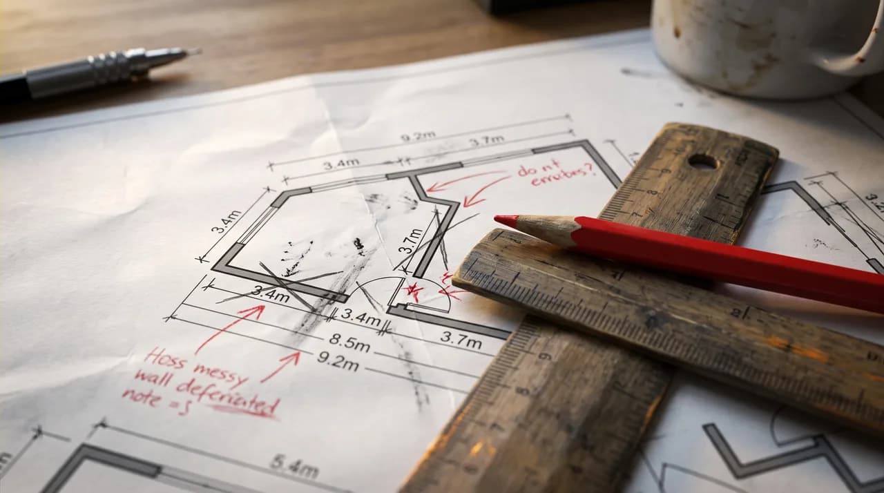
Few sentences are heard as often on construction sites and in planning offices as this one: "But we already have plans." And they really do exist: as a DWG file on the server, as a PDF in the building records folder, sometimes even neatly laid out and framed on the wall. And yet, time and again, it turns out in practice that these very plans are no use for the task at hand. Walls are somewhere else, heights are wrong, entire technical layers are missing. The plan looks like a reliable foundation, but it isn't.
This is not a matter of individual sloppiness; it is a systemic problem. CAD plans come into being over years, pass through many hands, and are copied, converted, and handed on. Along the way, they accumulate errors that no one sees anymore, because they disappear into the clean line drawing. Drawing on everyday surveying practice, this article shows why existing CAD plans are so often unusable, how to spot it, and why a fresh 3D survey usually turns out to be the more honest and more economical foundation in the end.
The Core of the Problem: As-Planned Is Not As-Built
Every plan created before the first shovel hits the ground describes a desired state. It shows how the building is supposed to be built, not how it actually ends up standing. Between these two states lie countless decisions made during the construction phase: a wall is shifted by ten centimeters because a duct was in the way, a door migrates, a niche is dropped, a lintel is built deeper than drawn. These deviations are entirely normal. Building is a process of continuous adaptation to reality.
The problem is not the deviation itself, but the fact that it almost never flows back into the plan. The execution planning remains the last documented state, and the as-built plan, which should actually show the constructed state, is in many projects simply never created. What sits in the folder as an "as-built plan" is in truth often just the old execution planning with a new stamp. The discrepancy between as-planned and as-built is thus built in before construction is even finished.
For B2B practice, this has tangible consequences. Anyone who calculates a renovation, a conversion, or a technical retrofit on the basis of such plans is planning against a state that never existed. The surprises then arrive reliably, only they show up once the contractor is on site and discovers that the component does not fit where the plan said it should sit.
On top of this comes a time-related effect that is often underestimated. Even an initially correct as-built plan ages. Buildings are not static objects; they are altered over their entire lifespan. Partition walls are added or removed, openings are cut, uses are repurposed. Each of these changes moves the documented state a little further from the real one. After two or three usage cycles, the original plan describes a building that no longer exists in that form at all.
Copy of a Copy: Inherited Errors in As-Built Plans
A second mechanism compounds the problem: plans are rarely drawn from scratch, but instead derived from older templates. For a conversion, the planner takes the existing as-built plan, draws in the new components, and delivers the result. That is efficient, and therein lies precisely the danger. Because every error contained in the template is carried over unchecked. It is not corrected; it is inherited.
Over several generations of conversions, this produces a plan that looks up to date at first glance, but whose geometric substance is in part decades old. The load-bearing interior wall was perhaps once measured incorrectly and has been twenty centimeters too thin in every subsequent plan ever since. A room layout that was traced by hand during an earlier digitization drags its inaccuracy through all later revisions. No one ever remeasured, because everyone assumed the template was correct.
It becomes especially treacherous at analog-to-digital breaks. Old paper plans were scanned in at some point and retraced in CAD, often on screen, by eye, using an assumed scale. This retracing looks clean, but bears only a rough relationship to the real dimensions in the building. The digital plan then carries the aura of precision, even though its origin is a crude hand sketch.
An underrated aspect, moreover, is the variety of sources from which a single as-built plan can be assembled. It is not uncommon for the floor plan, section, and detail to come from different revision states of different offices. At a quick glance they seem like a consistent piece of work, but in detail they sometimes contradict one another considerably. Anyone who relies on only one of the parts takes on its specific errors without even noticing the contradictions with the other parts. Only when the documents are overlaid do the inconsistencies come to light, and then the question arises which state one should actually believe.
The Wrong Scale and the Shifted Origin
Digital plans give the impression of being infinitely precise, since you can zoom in as far as you like. But the zoom says nothing about the correctness of the underlying geometry. A common and consequential error is an incorrectly set scale: the plan was scaled without a proper reference, so that a drawn length of ten meters actually corresponds to 9.80 meters or 10.30 meters. On a single wall, this is barely noticeable. Across the entire length of the building, the error adds up to a deviation that becomes genuinely expensive during construction.
Equally problematic are inconsistent or missing reference points. When different floors, components, or trades are referenced to different origins, the layers do not line up when superimposed. The floor plan of the ground floor and that of the upper floor are then shifted relative to one another without anyone noticing, until a riser or an elevator shaft suddenly fails to run through. If a defined coordinate system is missing entirely, the plan cannot be reliably linked to other data sources, such as cadastral data or the specialist planning of other parties involved.
These errors are practically invisible in the finished plan. They only reveal themselves when you hold the plan up against reality, that is, when you remeasure. But that is exactly what happens too rarely in the normal course of a project. People trust the file because it is digital and looks tidy. The shifted origin and the wrong scale are silent errors: they make no noise until they cost money on the construction site.
Missing Technical Layers: The Plan Shows Only Half the Truth
A floor plan that shows walls, doors, and windows seems complete. For the architecture, it may even be. But as soon as real interventions in the building are involved, crucial information is missing: the building services. Pipe routing, ventilation ducts, sprinkler lines, electrical runs, suspended ceilings, floor build-ups, all of this is in many existing CAD plans either not included at all or distributed across layers that were lost long ago.
The reason lies in the division of labor in planning. Architecture, structural engineering, and building services are handled by different offices, often in separate files. What ultimately lands with the owner or operator is frequently only the architectural plan. The specialist plans stay with the respective offices, are lost when there is a change, or exist only in a paper version that no one can find anymore. The facility manager who, years later, is looking for a pipe then stands in front of a plan that shows everything except what they need.
On top of this, building services in particular are permanently altered during ongoing operation. New server rooms, retrofitted air conditioning, relocated wiring, these interventions often take place without any plan update at all. Even if a complete building services plan once existed, after a few years of operation it no longer reflects the real state. For operation, maintenance, and conversion, however, a plan without reliable technical layers is at best half the truth.
Added to this is the problem of lost or unstructured layers. Even when technical information was originally captured, in many handed-over files it is no longer cleanly separated by trade. Layers were merged, renamed, or definitively flattened when exported to a PDF. What remains is an image without the structure that would make it usable for analysis. The operator can then still see that a pipe was drawn in somewhere, but can no longer reliably determine which medium it is or whether the information is still current.
The Fallacy of Precision: Nicely Drawn Is Not Verified
Perhaps the most dangerous misconception in dealing with CAD plans is equating a clean presentation with factual correctness. A precisely rendered plan with exact lines, clean dimensions, and a professional layout signals reliability. But the quality of the presentation says nothing about the quality of the survey behind it. A plan can look perfect and yet never have been verified against reality.
CAD software forces a precision that the data basis does not actually provide. Anyone drawing a wall has to enter a concrete value, say 4.25 meters. Whether this value was measured, estimated, or taken from an old template is not apparent from the finished plan. The number is there, sharp and unambiguous, and suggests a certainty that never existed. This apparent exactness is more deceptive than an obviously crude hand sketch, where everyone immediately knows they need to remeasure.
In practice, this leads to a dangerous chain of trust. The planner relies on the template, the estimator on the plan, the executing contractor on the estimate. No one in this chain has ever held the tape measure or the scanner to the wall. Everyone trusts a number whose origin no one knows anymore. Only on the construction site is it checked, and there every correction is at its most expensive.
What Unchecked Plans Really Cost
The real costs of unusable CAD plans arise not in the planning office, but in execution. An error that would have cost a few hundred euros during the survey quickly becomes a five-figure problem in the construction phase. When prefabricated components do not fit because the opening is different from the plan, they have to be reworked or reordered. When a pipe runs where the plan said there should be space, the trade stands idle until a solution is found.
On top of the direct material costs come the more expensive knock-on costs: extended construction time, standstill of coordinated trades, change orders, replanning under time pressure. A single wrong reference point can send an entire schedule chain sliding. And because such problems usually surface right in the middle of execution, there is rarely time for clean alternatives; people improvise, and improvisation is expensive. The effort originally saved on a proper survey comes back to bite many times over.
Equally real, though harder to quantify, is the liability risk. Anyone who prepares tenders, quantity take-offs, or permit documents on the basis of faulty as-built data bears responsibility for the consequences. Disputes over change orders, conflicts with executing contractors, and, in extreme cases, demolition tie up time, money, and nerves. The plan that was supposed to save costs at first glance becomes the most expensive item in the project, because no one distrusted it in time.
How a Fresh 3D Survey Makes the Foundation Reliable Again
The only way to resolve the built-in uncertainties of old CAD plans is a direct comparison with the real building. A 3D survey via laser scanning captures the state as actually built, not the planned state, not the inherited one, but the one that really stands on site today. In a short time, the scanner records millions of measurement points and generates from them a point cloud that maps the building to the millimeter. What was measured is thereby documented in a traceable way, instead of being taken from an unknown source.
From this point cloud, clean 2D plans, sections, and elevations or a complete BIM model can be derived, all based on the same, verified data state and with a uniform, defined coordinate system. The scale is correct because it comes from the measurement and is not estimated. The reference points sit right because the entire building was captured in a common reference system. And the technical layers are there, because the scanner does not distinguish between architecture and building services, but simply records everything that is visible, including visible pipes, ducts, and fittings.
What is decisive is the character of this data: it is honest. A point cloud shows the building as it is, with all its irregularities, the slightly crooked wall, the deviating ceiling height, the offset that no old plan knew about. That may feel uncomfortable at first, but it is exactly the point: you finally plan against reality and not against a wishful notion. For architects, planners, and facility managers, this means calculation certainty, fewer change orders, and as-built documentation you can still trust in ten years, provided future changes are consistently fed back into the model.
A further advantage lies in verifiability. Because the point cloud preserves the entire captured space, dimensions can be taken off after the fact at any time, without having to measure on site again. If a new question arises during planning, how high is the lintel at this opening, how deep does that duct run, the existing scan supplies the answer. You no longer work with a reduced interpretation of the building, but retain the complete measured record as a reference that can be queried at any time. This decouples data collection from the individual question and makes the investment usable across many later project phases.
It is important here to take a realistic view of the method's limits. A laser scanner captures what it can see; pipes behind closed walls or in inaccessible shafts remain hidden from it and must, if needed, be recorded through supplementary methods. A model, too, remains reliable only as long as it is maintained. The value of a 3D survey therefore lies not in the one-time capture alone, but in the decision to consistently track future conversions in the model. This turns a snapshot into permanently dependable as-built documentation.
Conclusion
CAD plans are often unusable not because someone worked carelessly, but because they accumulate errors by design: they show the planned instead of the built state, inherit inaccuracies from old templates, carry the wrong scales and shifted origins, and lack entire technical layers. Their clean presentation conceals the fact that they were never checked against reality. The real risk lies in blindly trusting this apparent precision.
Anyone who depends on reliable as-built data, whether for conversion, renovation, retrofitting, or operation, cannot avoid a check against the real building. A fresh 3D survey is not a luxury here, but the more economical option: it costs a manageable amount at the outset and spares the far higher costs that wrong plans cause in execution. The honest question is not whether you have plans, but whether you can trust them. And that question can only be answered by measuring.